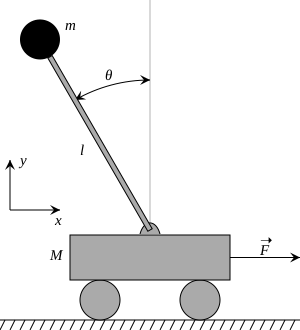
1. Mechanical Design
I knew I wanted the project to be on a linear sled controlled by the stepper motor. I believed it would be an easier introduction to control over a rotational pendulum. I used Fusion360 for this project as an opportunity to learn the software and add to my portfolio.
The first part that I designed was the sides of the mechanism. The intent was to hold the 8mm rods, have slots for mounting components, space for the control belt, and potential for mounting to the table. The final design is shown below.
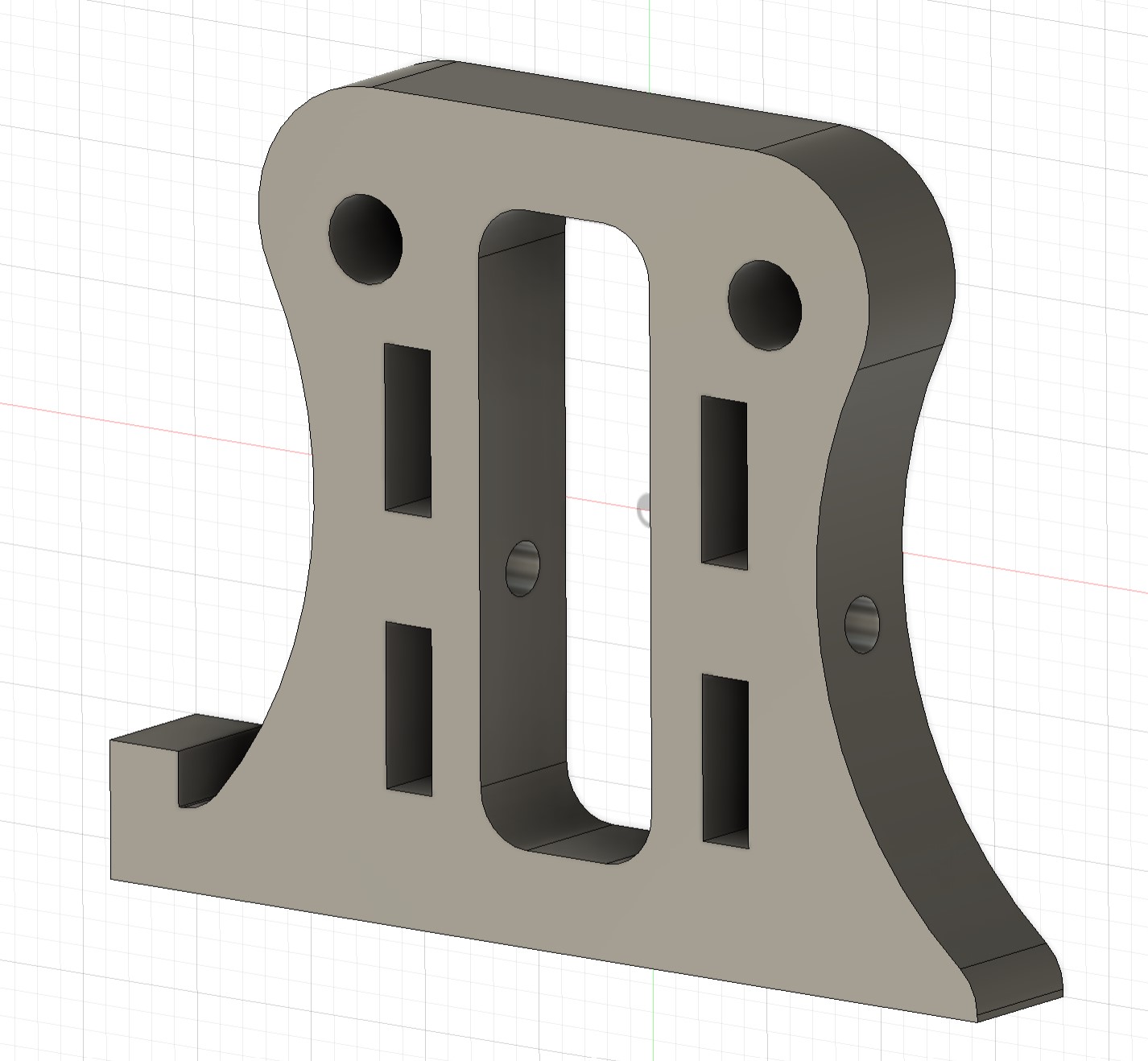
Pendulum Stand Side
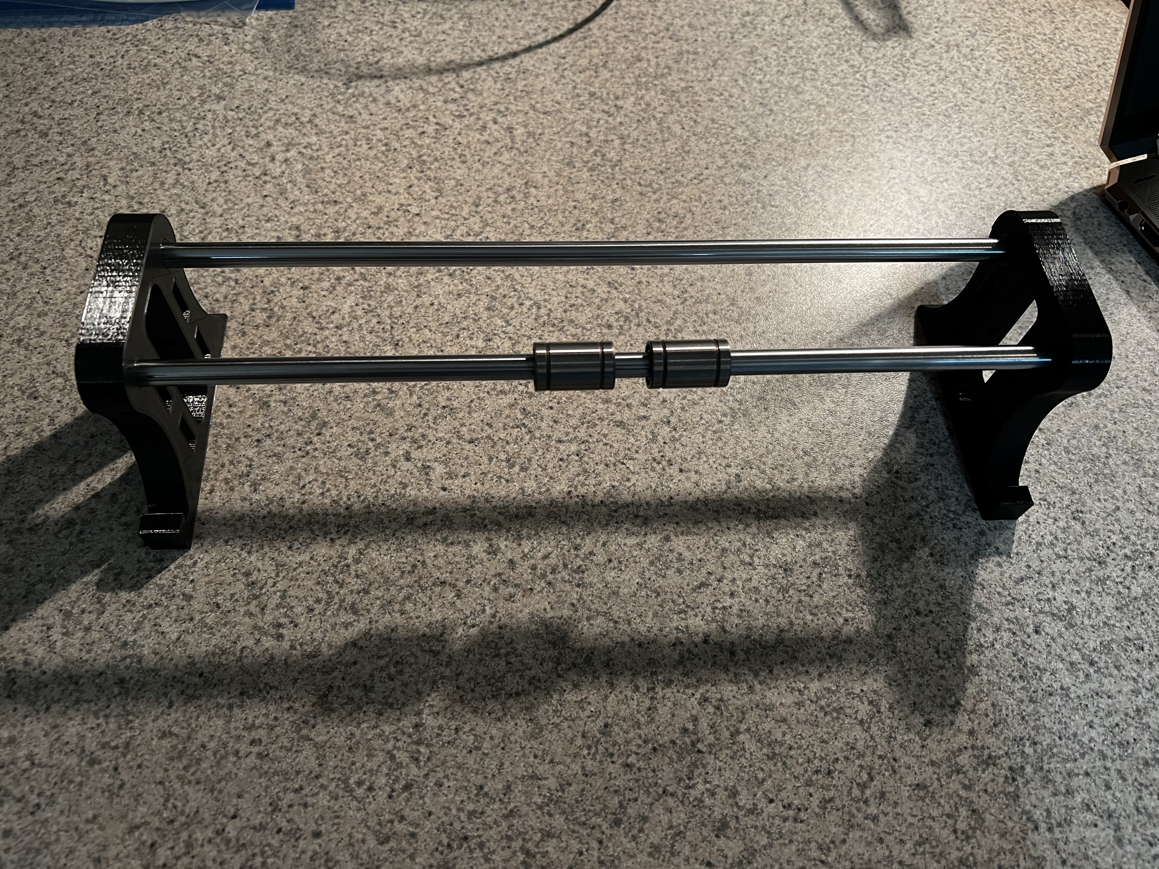
Sides Printed with Linear Rods
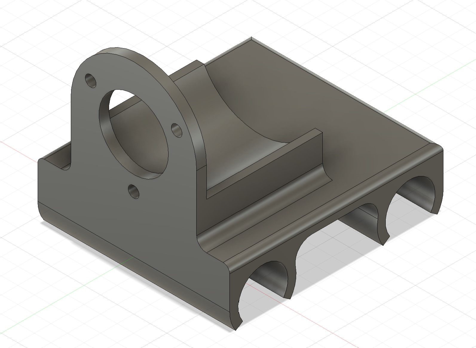
After I printed the sides, the next design was the mount for the stepper motor. I wanted this to attach to the side with the GT2 gear sitting in the middle of the stand. The original print had the legs a little too short, so a spacer was later printed and added onto the bottom. The CAD was adjusted to correct this.
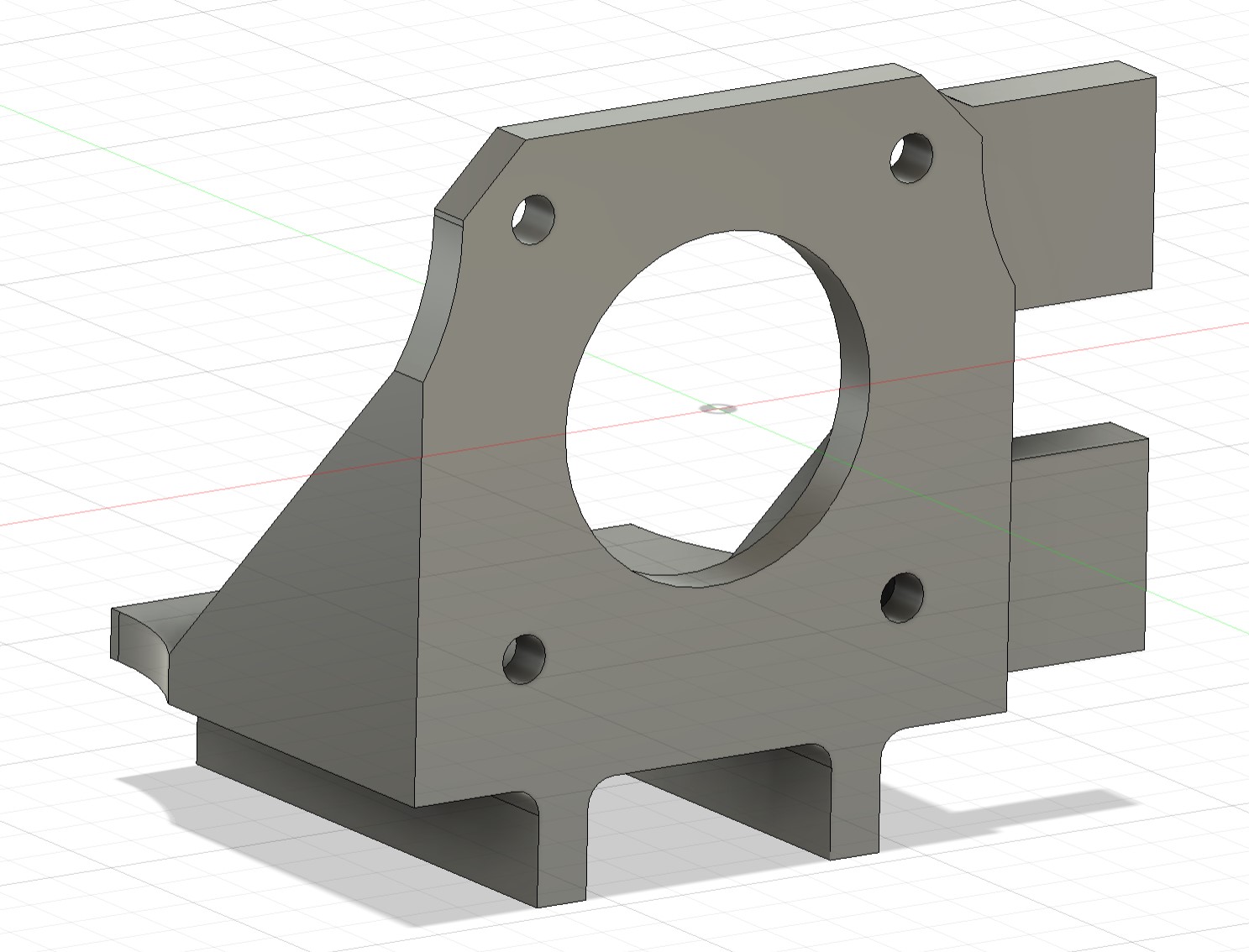
Stepper Motor Mount
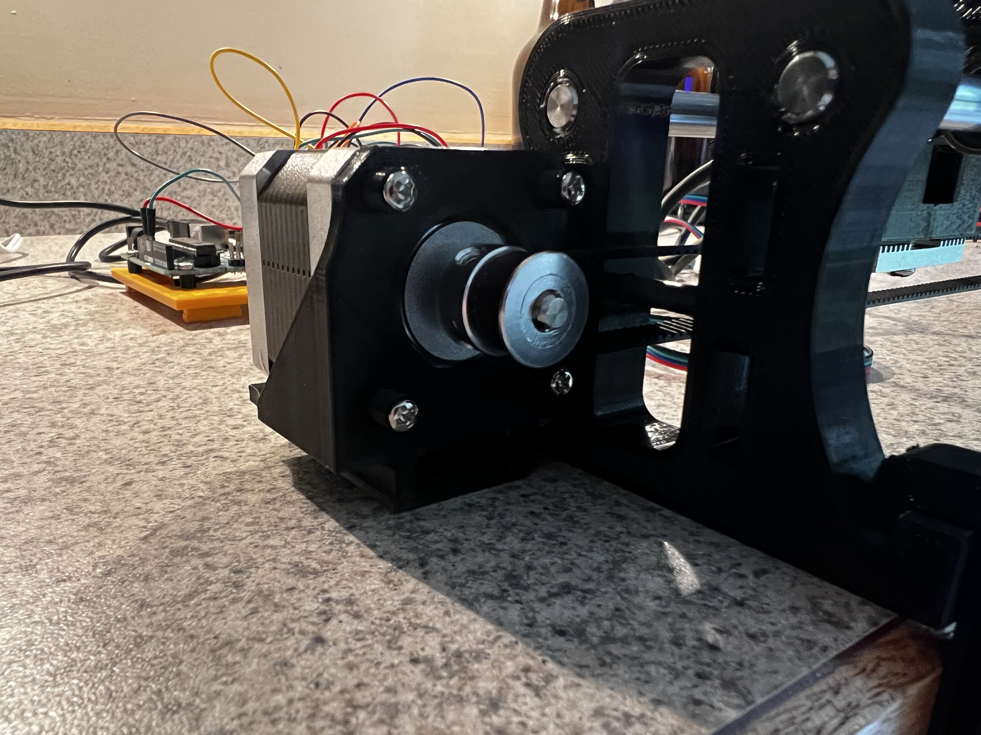
Printed Stepper Mount
The next item I designed was the sled for the encoder. To ease the printing process, the attachment for the belt was printed separately. The only issue that arose was I did not include enough tolerance in the mounting holes for the encoder, and these were drilled out for a better fit. To help with attaching the belt to the sled, a threaded insert was placed in the standoff.
Encoder Cart
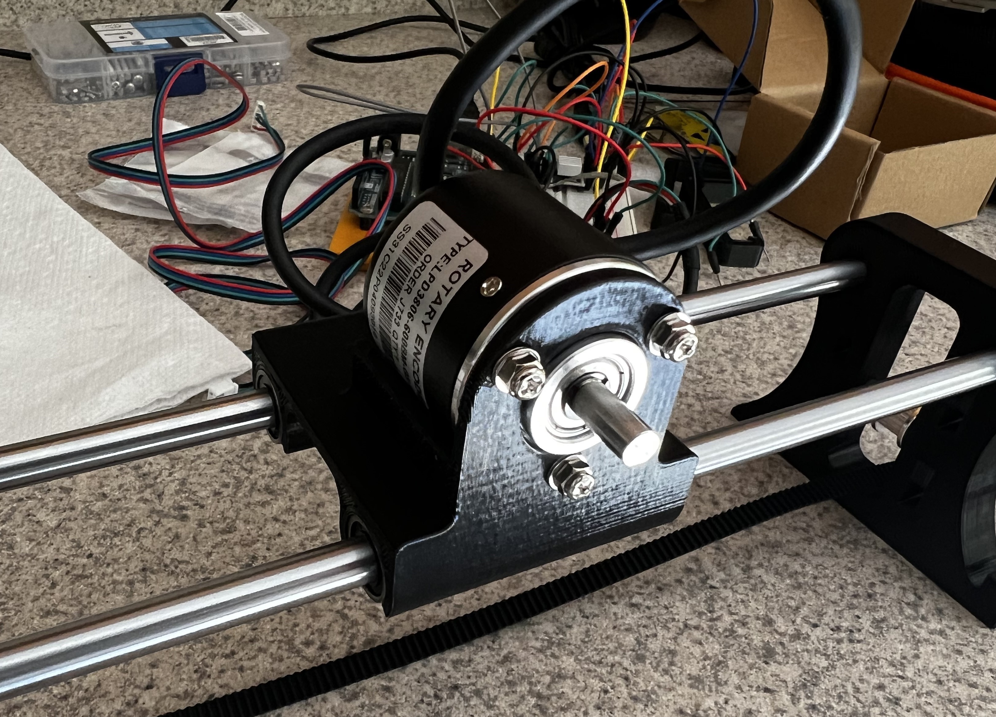
Printed Encoder Cart
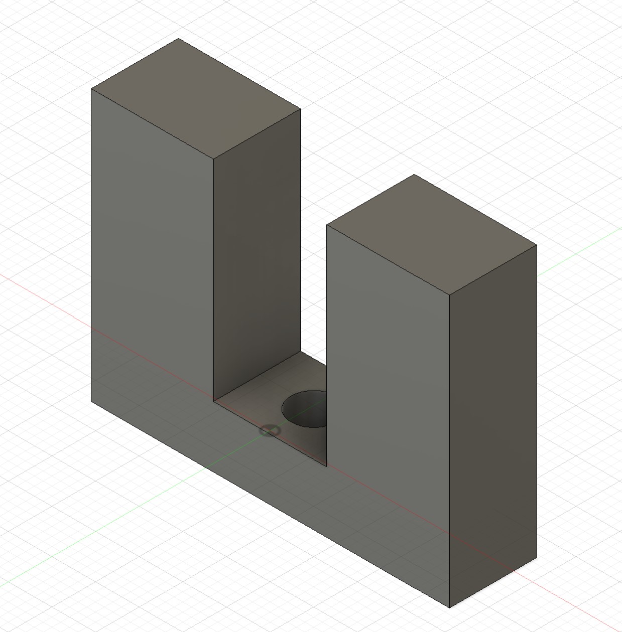
Sled Standoff
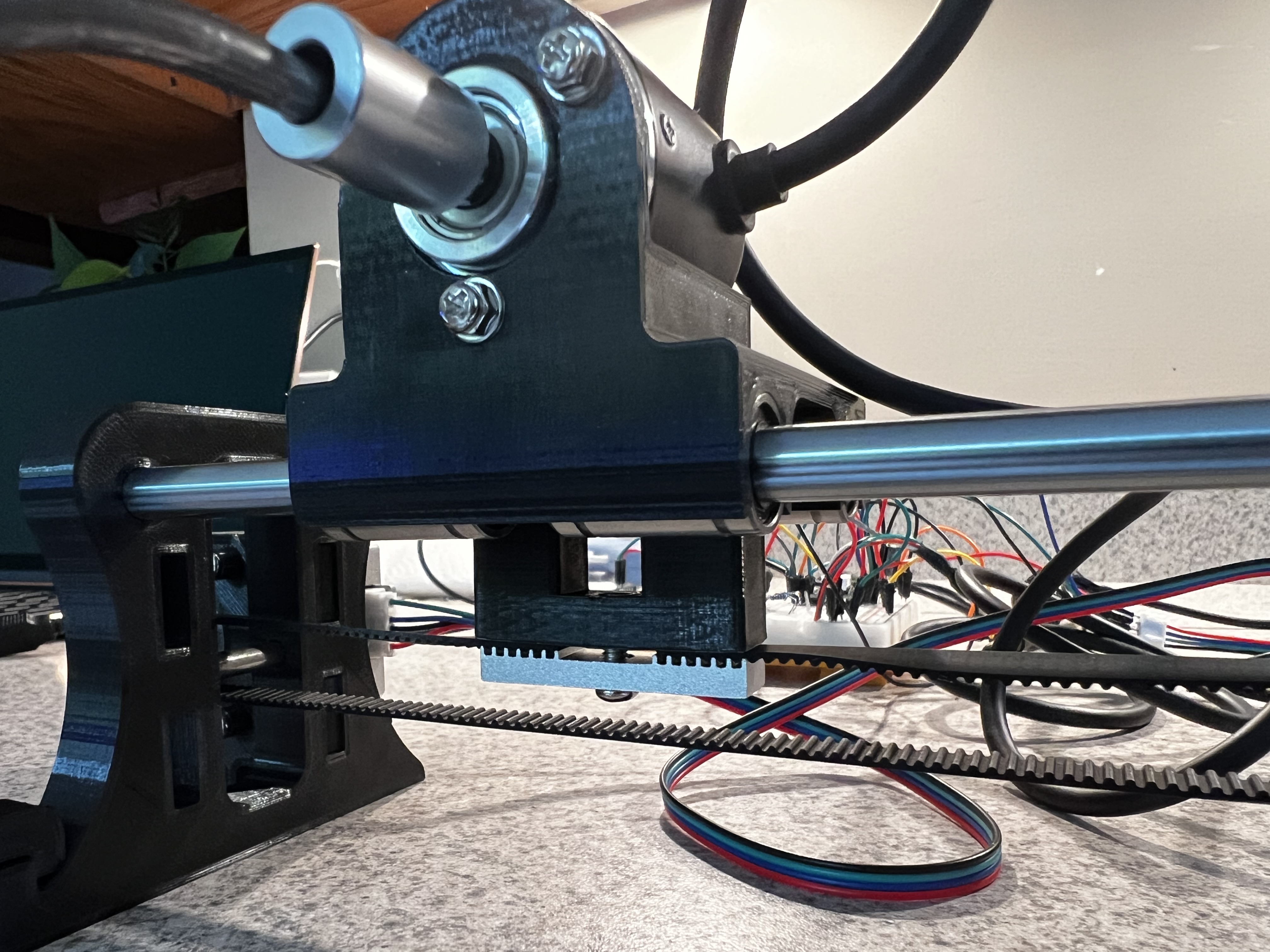
Belt Connection
The final design is shown below. As of now, it seems to work well, however, I may need to add a cap to the end of the sides to prevent the rods from sliding under the tension of the belt. Currently, the friction fit seems to enough, but this may worsen over time. The original intent was to add a cap, but this was forgotten in the first iteration.
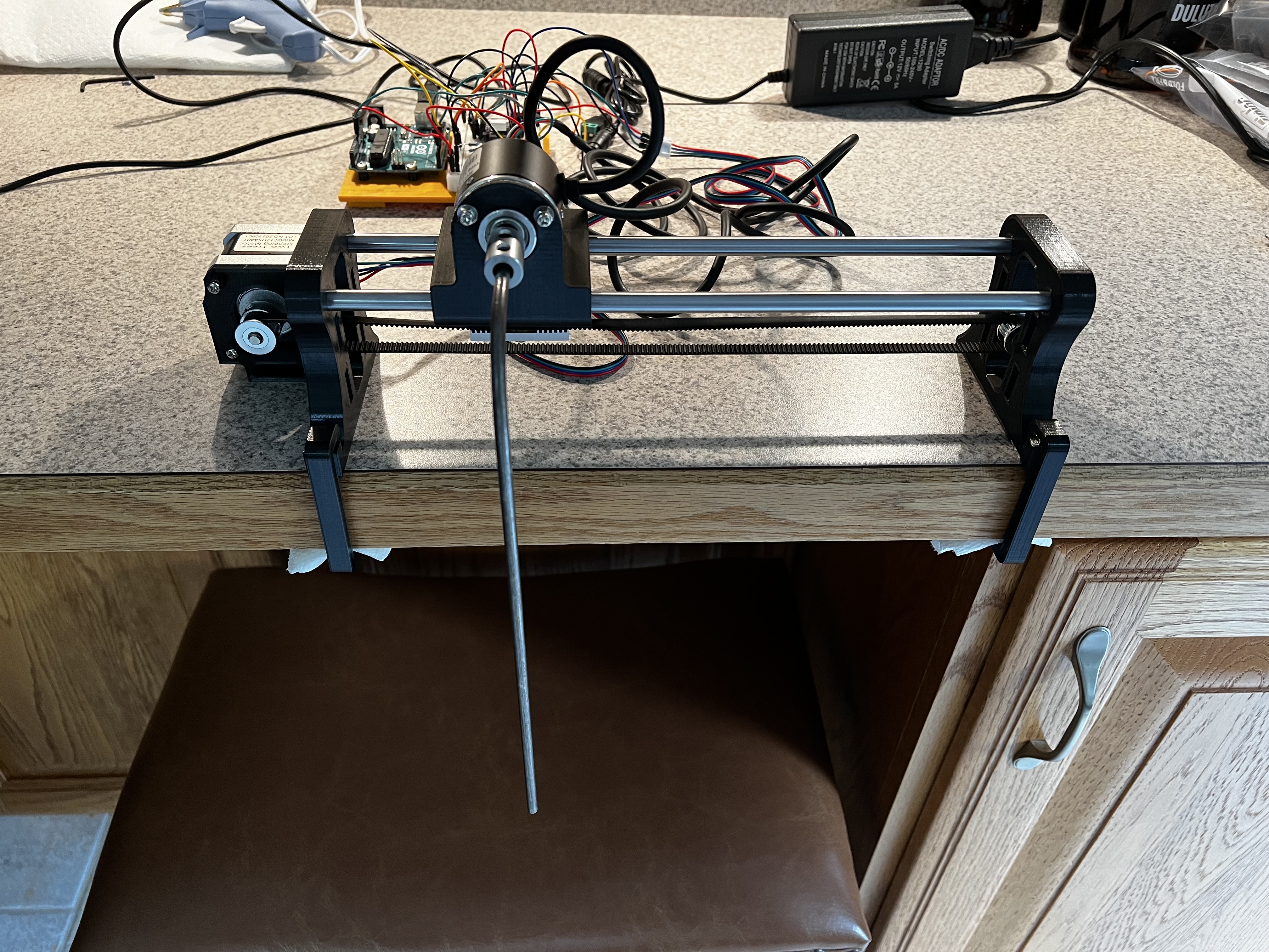
Final Design
2. Stepper Motor Wiring
To drive the stepper motor with the Arduino, I am using the DRV8825 stepper motor driver. I chose this one for the Nema17 motor because it was capable of providing a higher current than the A4988 and should have better microstepping, although this is not used currently.
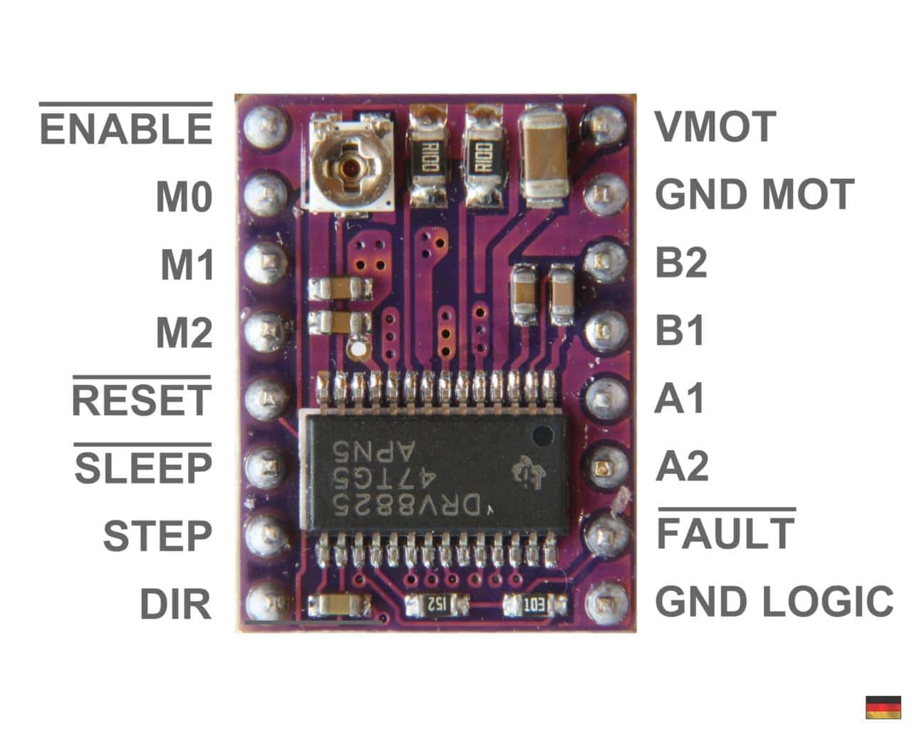
DRV8825
The website,
Last Minute Engineers, was extremely helpful in wiring and setting the motor driver. To start, I connected my 12V power supply to the breadboard and then the positive to the VMOT pin and ground to the GND MOT pin, bridging the two with a 100μF capacitor to protect against voltage spikes. I then connected the ground of the microcontroller to the GND LOGIC pin of the driver.
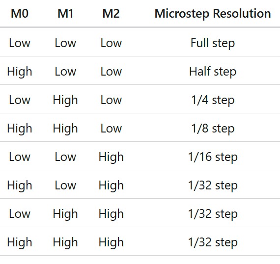
The M0, M1, and M2 pins are to adjust for microstepping. I left these alone so that the driver was set to full stepping.
To control the motor, I connect pin 5 of the arduino (PWM capable) to the STEP pin of the motor driver, and pin 4 of the arduino to the DIR pin of the driver. Then, I connected the SLEEP, RESET, and FAULT pins of the driver to the 5V supply from the microcontroller so the board will be enabled. These have options to control later to add safety features that may shut down the driver.
The next step was to set the current limiter on the driver before connecting the motor, which is what differed from Last Minute Engineers. I did it differently to avoid burning out the motor accidentally. To set the current limit, there is a potentiometer that allows adjustment when measuring the voltage between the potentiometer and the GND LOGIC pin. The voltage should be set so Vref = Current Limit/2. I set mine to 0.7V for a small buffer of the 1.5A rated Nema17 motor.
After the current limit was set, I connected the motor wires to the A1, A2, B1, and B2 pins of the driver. The phases of the motor must go together (A or B) for the motor to work properly. I had originally had these wired differently (same way it came out of the motor) and the motor tried to move but could not. After swapping the wires around, the motor worked perfectly (an issue that took too long to figure out).
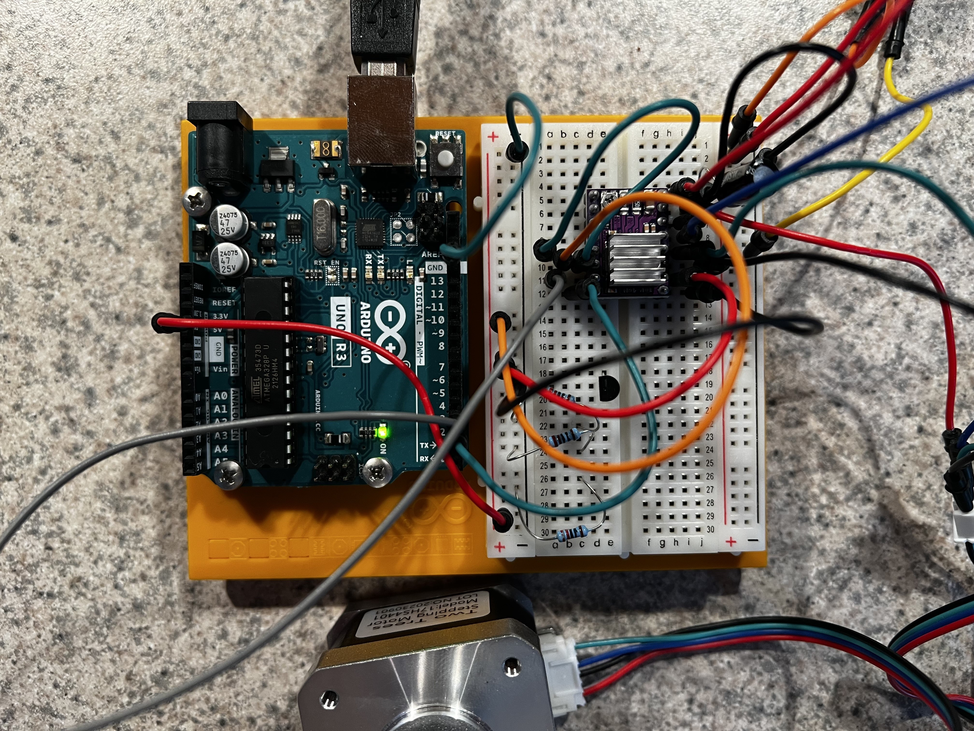
Stepper Motor Wiring
3. Rotary Encoder Wiring
Lorem ipsum dolor sit amet, consectetur adipisicing elit, sed do eiusmod tempor incididunt ut labore et dolore magna aliqua. Ut enim ad minim veniam, quis nostrud exercitation ullamco laboris nisi ut aliquip ex ea commodo consequat.