1. Original Design & Tooling
The original reflector design already existed, but had poor CAD practice behind it; asymmetry, broken features, and no design for manufacturing. I corrected the model, added features like glue-application holes, and applied DFM principles (minimum bend radius, internal radii, minimum hole size) so it could actually be produced reliably.
We used Fotofab to electroetch the profile and precision-form the pieces, which let us attach the electroformed reflectors to the PV carriers. Each reflector required four gluing operations to the CPCs (compound parabolic concentrators) plus four more for the mounting tabs; eight per part, or roughly 1,200 individual gluing operations across the ~150-piece batch. I also swapped the reflective material to something cheaper and easier to manufacture than the specialized material used before, and designed tooling to bend the sheet metal reflectors.
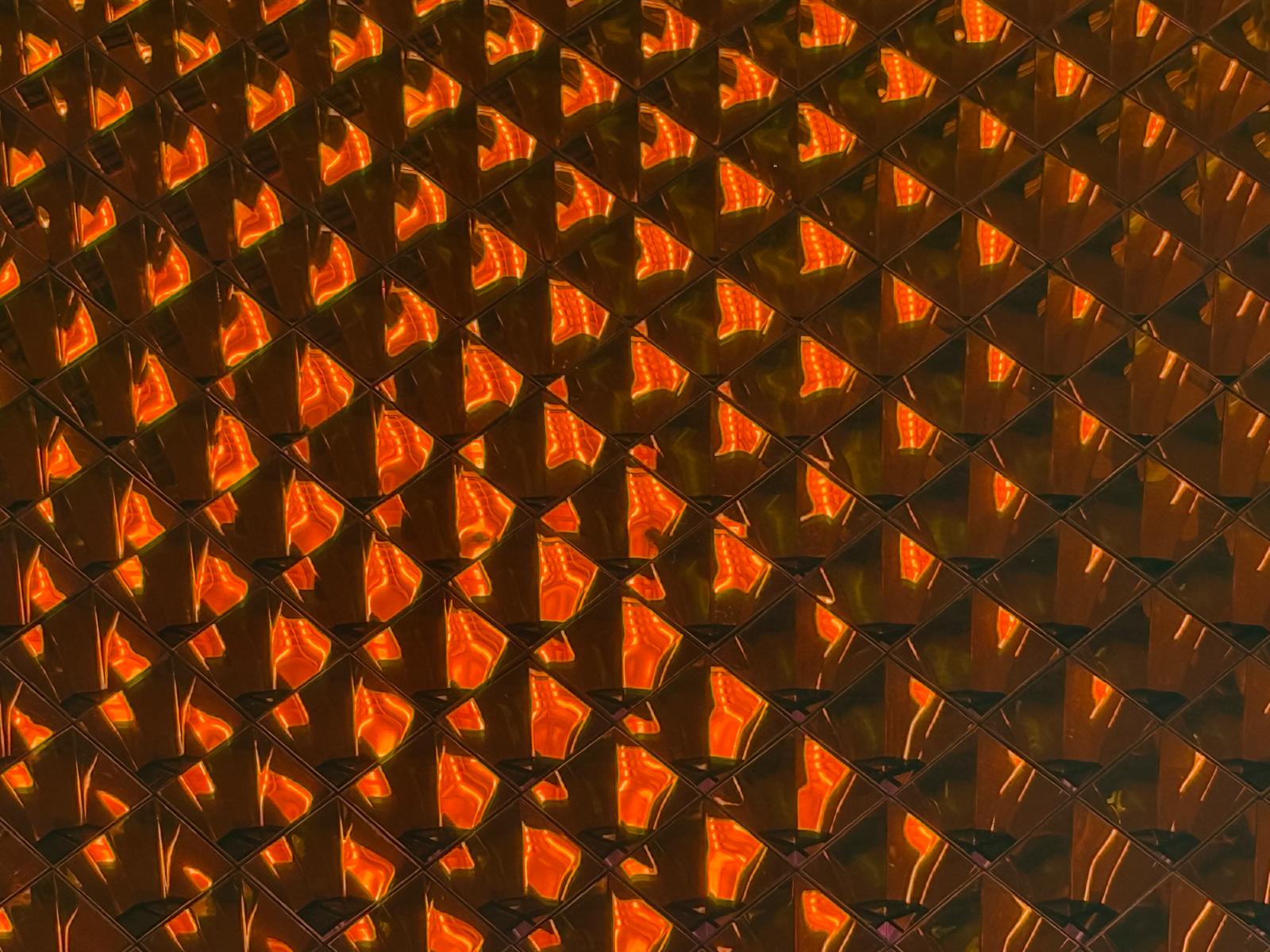
Array of original CPCs
2. FTPR Redesign
Once the receiver moved to a drone platform, weight became the top priority; ahead of optical efficiency and surface quality. The original gold-plated, electroformed reflector had a complex wall shape for angular effectiveness, but was heavy. I designed a new reflector (FTPR; flanged truncated pyramidal reflector) out of a commercial reflective metal, and combined the adapter hat with the reflector itself, which roughly cut the number of assembly operations in half.
A coworker ran the optical simulation to find the optimal wall angle; I owned the product from design through implementation; CAD modeling, drawings, and working with suppliers.
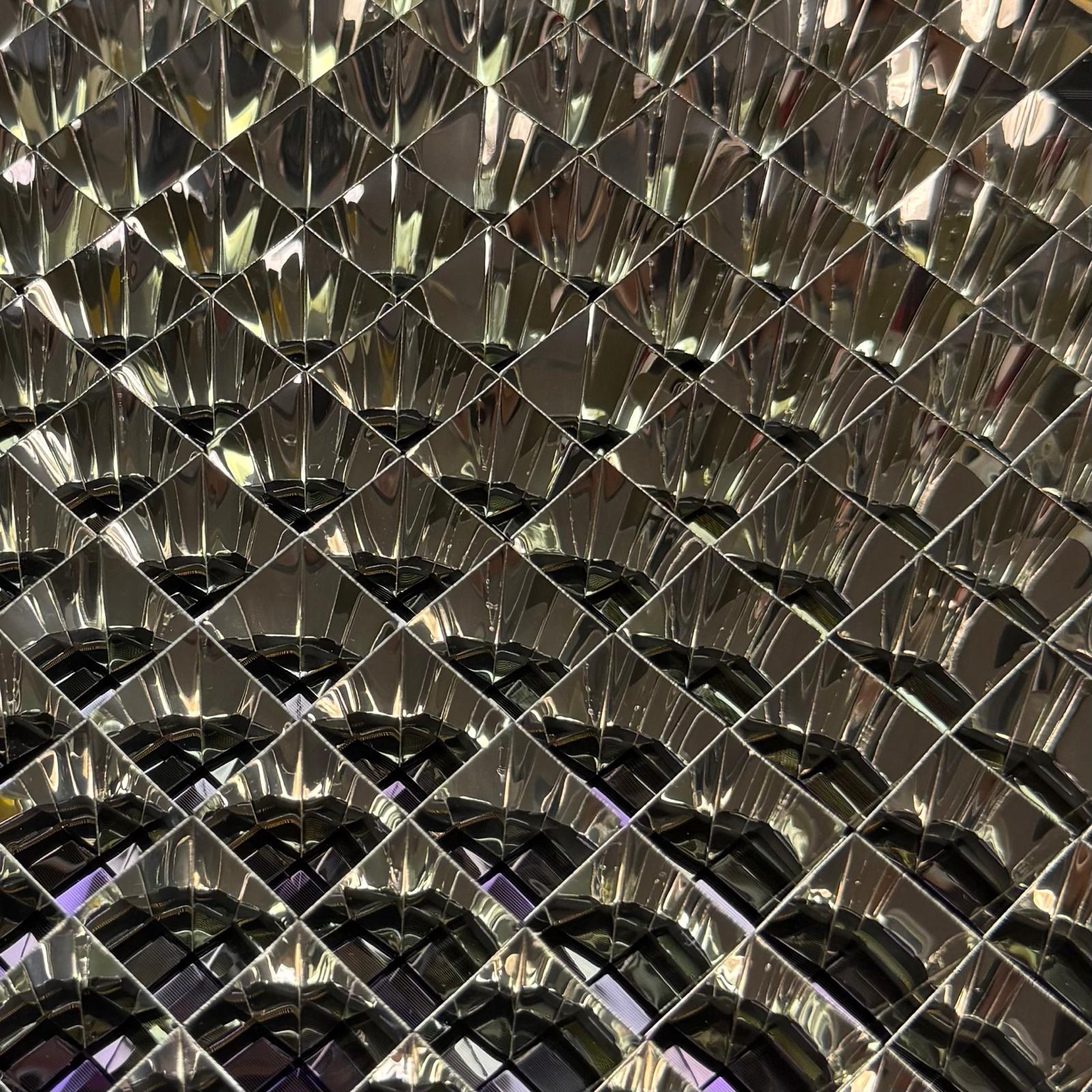
New FTPR array
3. Supply Chain & Quality
The FTPR went through a multi-supplier chain: one supplier formed the part, it was shipped out to have the seam laser welded, and then shipped again to our facility in Kent for quality inspection and assembly. I worked closely with the manufacturing supplier through a lot of back-and-forth to reach a functional part, and inspected incoming parts using an optical comparator to check dimensions and tolerances.
4. Cleaning Process
I developed a process to safely and effectively clean grease and fingerprints off the reflective surfaces without damaging them. I built a jig to hold the reflectors while flushing them with degreaser, rinsing in tap water, and finishing with a distilled water rinse. I confirmed the process didn't affect the reflective surface by testing cleaned parts with a spectrometer.
5. Optical & Thermal Validation
I designed and set up an optical test on the optics table to validate the geometry of the FTPR. I also ran thermal testing to confirm the FTPR could handle the higher temperatures it would see in the receiver — the manufacturer had already validated the material, but the geometry still needed internal validation, which was required for TRL7.
6. Folding & Mounting Tooling
I designed tooling to fold the reflectors. The process itself wasn't implemented in-house, but our supplier used it to improve their tolerancing and consistency; parts had previously been inconsistent and out of spec.
I also designed tooling to attach the FTPRs to the receiver. Because the new reflectors were so much lighter, they were hard to keep aligned while the adhesive cured, and if one tipped over during assembly it risked damaging roughly $250k worth of PV cells on the receiver. I built a jig that mounted to the board with a grid to hold and align each FTPR in place, which made placement slightly more involved but drastically reduced the risk of knocking over the reflectors and kept everything aligned through cure.

Alignment Tool
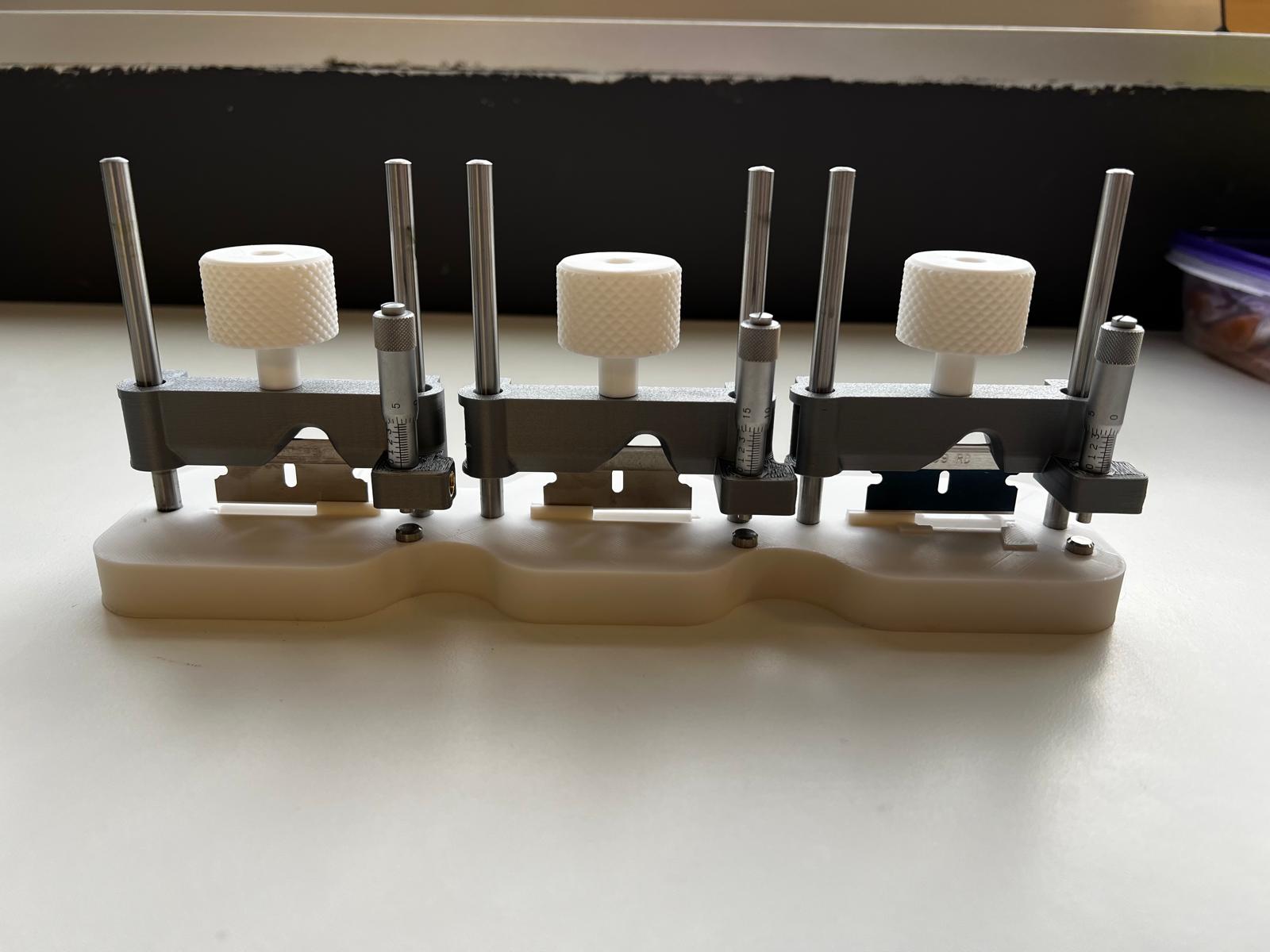
Forming Tool